
 English
 Español
 Deutsch
 русский
The Direct Answer: Mould Design Is the Root Cause of Most Production Problems
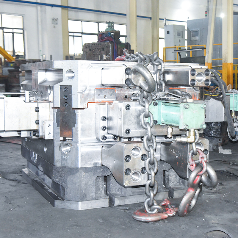
Die casting mould design determines production success because roughly 70% to 80% of casting defects — including porosity, cold shuts, warping, and short fills — originate from mould design decisions made before a single part is ever cast, not from the casting process itself. Gating layout, venting placement, cooling channel design, and cavity geometry collectively control how molten metal fills the cavity, how quickly it solidifies, and how easily the finished part releases from the tool. Once a die is cut, these design choices are locked in for the life of the tool, which is why errors discovered after production starts are expensive and often impossible to fully correct.
If you are launching a new die casting program, the highest-leverage investment you can make is thorough design review before tooling begins — not troubleshooting after the first production run reveals defects. A well-designed mould directly reduces scrap rate, shortens cycle time, and extends tool life, while a poorly designed one can undermine even the best casting machine and highest-quality alloy.
Core Structural Elements of a Die Casting Mould
A die casting mould consists of several interacting systems, each of which must be engineered correctly for the tool to produce consistent, defect-free parts.
Cavity and Core
The cavity defines the external shape of the part, while the core forms internal features such as holes, bosses, or ribs. Precision machining of both surfaces, typically to tolerances within 0.02 to 0.05 mm, directly determines the dimensional accuracy of every part produced from the tool.
Gating System
The gating system — comprising the sprue, runners, and gates — controls how molten metal enters the cavity. Gate location and size determine fill pattern, flow velocity, and where turbulence or air entrapment is most likely to occur, making it one of the single most influential design elements in preventing porosity.
Venting and Overflow System
Vents allow trapped air and gas to escape as molten metal fills the cavity, while overflow wells capture the leading edge of metal flow, which often contains oxides and cold metal that would otherwise create surface defects if trapped within the part.
Cooling Channels
Internal cooling channels regulate die temperature and control solidification rate. Uneven cooling channel placement is one of the most common causes of warping and dimensional inconsistency between cavities in multi-cavity tools.
Ejector System
Ejector pins push the finished part out of the die after solidification. Poor ejector pin placement can cause part distortion, surface marks, or sticking, particularly in parts with deep ribs or thin walls.
How Specific Design Choices Prevent (or Cause) Common Defects
Understanding the direct link between mould design decisions and resulting defects helps explain why design review matters more than adjusting process parameters after the fact.
| Defect | Typical Design Root Cause | Design Fix |
|---|---|---|
| Gas porosity | Insufficient or poorly placed vents | Redesign vent layout along last-fill areas |
| Cold shuts | Gate too small or poorly positioned | Increase gate size, adjust flow path |
| Warping | Uneven cooling channel distribution | Rebalance cooling circuit layout |
| Sticking or drag marks | Insufficient draft angle | Increase draft to at least 1–2 degrees |
| Flash | Poor parting line fit or clamping force mismatch | Refine parting line machining tolerance |
In most cases, correcting these issues after tooling is complete requires costly die modification or, in severe cases, cutting a new tool — reinforcing why upfront design validation is far more cost-effective than post-production troubleshooting.
Mould Material Selection and Its Impact on Tool Life
The tool steel used to construct the mould directly affects how many production cycles the die can withstand before thermal fatigue cracking, known as heat checking, degrades part quality.
- H13 tool steel: The industry-standard choice for aluminum die casting, offering a good balance of thermal fatigue resistance and machinability, typically supporting 100,000 to 300,000 shots depending on part complexity and maintenance practices.
- H11 tool steel: Similar properties to H13 with slightly different heat treatment characteristics, sometimes preferred for specific cavity geometries.
- P20 steel: A lower-cost option generally reserved for prototype tooling or very low-volume production runs, since it offers reduced resistance to thermal cycling.
Selecting an inadequate steel grade to save on upfront tooling cost frequently results in premature die failure, unplanned downtime for repairs, and inconsistent part quality as the cavity surface degrades — costs that typically far exceed the initial savings.
Single-Cavity vs. Multi-Cavity Mould Design
Cavity configuration is a critical design decision that affects both production economics and part consistency, and should be selected based on volume requirements and part tolerance needs.
| Factor | Single-Cavity | Multi-Cavity |
|---|---|---|
| Tooling cost | Lower | Higher |
| Output per cycle | Lower | Higher |
| Dimensional consistency | Easier to maintain | Requires balanced cavity design |
| Best suited for | Prototypes, low volume | High-volume production |
Multi-cavity moulds require significantly more precise gating and cooling balance to ensure every cavity fills evenly; an unbalanced design can result in some cavities producing acceptable parts while others consistently show defects, effectively reducing usable output even though the tool appears to be running normally.
Design for Manufacturability: Getting It Right the First Time
Applying design-for-manufacturability (DFM) principles during the mould design phase — not after the first sample run — is the most reliable way to avoid costly rework.
- Uniform wall thickness: Keeping walls between 1 mm and 4 mm promotes even cooling and reduces the risk of shrinkage porosity at thick sections.
- Adequate draft angles: A minimum of 1 to 2 degrees on vertical surfaces ensures the part releases cleanly without dragging or damaging the cavity surface.
- Generous fillet radii: Rounding internal corners to at least 0.5 mm reduces stress concentration and improves metal flow during filling.
- Strategic parting line placement: Positioning the parting line to minimize visible flash on cosmetic surfaces reduces secondary finishing labor.
- Simulation before cutting steel: Mould flow simulation software can identify fill imbalances, air traps, and hot spots before the die is machined, catching design flaws when they cost far less to fix.
Maintenance Practices That Protect Long-Term Mould Performance
Even a well-designed mould requires disciplined maintenance to sustain part quality across its full production life. Regular cleaning of vents and overflow wells prevents gas buildup that leads to porosity, while routine inspection for heat checking on cavity surfaces allows minor cracks to be addressed through polishing or welding repair before they propagate and affect part cosmetics. Tracking shot count against the expected tool life helps production teams plan preventive maintenance or refurbishment before unexpected failures disrupt a production schedule, and consistent use of the correct release agent and cooling parameters helps preserve the cavity surface finish that the original mould design was engineered to produce.


 1 Building No.1 No.226. Tiantaishan Road, Daqi street. Beilun District, Ningbo City, Zhejiang Province, China
 +86-15967858563
