
 English
 Español
 Deutsch
 русский
Every aluminium part that leaves a high pressure die casting machine carries the fingerprint of a single piece of tooling: the die casting die. It looks like two heavy blocks of steel, but inside it holds a complete miniature system of runners, overflows, cooling lines, ejector pins and slides, fitted together to tolerances measured in hundredths of a millimetre. Change the die and the same machine will produce an oil pan, a base station housing, or a structural part for an electric scooter.
This guide walks through the whole subject from a workshop point of view: what a die actually is, which components sit inside it, how the main types differ, how a design moves from a drawing to a running tool, which steel grades hold up best, why dies fail, and what keeps a die alive across a long production run.
What Is a Die Casting Die?
A die casting die is a reusable metal tool, usually built from two or more blocks of heat treated steel, that closes to form a cavity matching the finished part. Molten metal is pushed into that cavity under pressure, held there while it solidifies, and then the die opens and the casting is ejected. The same cavity can repeat that cycle many thousands of times.
What separates a die from other casting tools is pressure and speed. In high pressure die casting, molten aluminium is driven into the cavity in a fraction of a second while the machine clamps the two halves together with a very large closing force. That creates several hard constraints:
- The tool has to be rigid enough to resist repeated clamping force and the impact of the incoming metal.
- The cavity fills in milliseconds, so the air already inside it must have somewhere to escape at the same moment.
- Die temperature has to be managed carefully, because a die that runs too hot or too cold will drift out of tolerance surprisingly quickly.
- The parting line has to seal tightly, otherwise metal flashes out along the edges under pressure.
Those four constraints explain almost every design decision described in the rest of this article.
In one line: a die casting die is a shape former, a heat exchanger, an air vent, an ejection mechanism and a pressure vessel, all built into two blocks of steel.
It is also worth saying what a die is not. It is not permanent. The parting line wears, the gate area develops heat checking cracks, ejector pins bend, slides seize. Die life is counted in shots, meaning complete clamp and eject cycles, and a maintenance plan matters just as much as the original design.
What Sits Inside a Die Casting Die
A die is usually described as a single object, but it is really a stack of subsystems. Each one has a job, and each one can be the reason a part comes out wrong.
Cavity and core inserts
These are the two blocks of steel whose gap becomes the part itself: the cavity forms the outer surface, the core forms the inner. They are normally made as replaceable inserts rather than cut directly into the die base, because they take the most wear and sometimes need to be swapped when a design changes.
Runner and gate system
The sprue, runners and gates form the path the metal takes to reach the cavity. Their location, cross section and angle decide whether the metal fills the cavity smoothly or blasts in and traps air against a far wall. In practice, the gate is the part of a die that gets modified most often.
Overflow and venting
Overflow wells sit at the far end of the cavity to catch the first, dirtiest metal and any trapped oxides. Thin vent channels beside them let air out without letting metal through.
Cooling and thermal control
Drilled or machined water lines run through the cavity and core inserts to pull heat out of the steel after every shot. Well placed lines keep the die at an even temperature; poorly placed lines leave hot spots that cause shrinkage porosity and soldering.
Ejection system
Ejector pins, sleeves, plates and return springs push the casting off the core. Balance matters as much as force here. Pins grouped in one small area will distort the part before they free it.
Base, guidance and slides
The die base holds everything together and carries the main clamping load. Guide pins and bushings keep the two halves aligned, while slides and lifters release undercuts. Slides are the components most likely to seize if lubrication is neglected.
Types of Die Casting Dies
Dies are usually classified by how many cavities they carry and what stage of production they serve. The choice is driven by part size, annual volume, and how much variation the customer can accept between parts.
Single cavity die
One casting per cycle. The right answer when the part is large, volumes are moderate, or quality requirements are tight enough that cavity to cavity differences are not acceptable.
Multiple cavity die
Two or more identical cavities inside one base. Unit cost drops, but filling balance becomes harder and each cavity needs its own venting considered separately.
Unit die
Cavity inserts are mounted into a standardised frame so different parts can share the same base. A common arrangement when order quantities are modest and product variants change often.
Combination die
Several different cavities in one base, producing more than one part per cycle. Useful for left and right hand versions, or for a pair of components that are always assembled together.
Prototype die
Built quickly, often with softer steel or a simplified structure, to validate shape and fit. Life is limited, but it produces genuine castings before the design is frozen.
Production die
The fully engineered tool: correct steel, full cooling, balanced ejection, replaceable inserts, and a design intended to run for tens of thousands of shots or more.
From Drawing to Running Die: The Sequence That Works
Most problems in a die can be traced back to a decision made in the first two steps below. The order matters as much as the individual tasks.
1. Drawing review and feasibility check
Before anything else, establish the alloy, the annual volume, the critical tolerances and what the part actually does. Some requirements marked on a drawing can be met as cast, and do not need to be pushed onto machining.
2. Parting line strategy
Where the die splits is the decision everything else follows from. It determines how the part releases, where slides go, which surfaces are visible, and where the gate is allowed to enter.
3. Runner, gate and vent layout
Gate position, runner section, overflow placement and vent channels are defined here. Gate area and metal velocity should be calculated from wall thickness, not chosen by habit.
4. Filling simulation
Simulation shows where air will be trapped, where the metal will run cold, and where shrinkage will appear, all before any steel is cut. It should be used to change the design, not to explain it afterwards.
5. Detailed 3D die design
Structure, slides, ejector layout, cooling circuits and all fits are finalised. Corrections at this stage cost hours; the same corrections after machining cost weeks.
6. Steel purchase and rough machining
Cavity and core blocks are roughed out with finishing allowance left on. The traceability of the steel batch matters as much as the grade itself.
7. Heat treatment and finishing
Hardening and tempering set the final balance of hardness and toughness. Finish milling, grinding, wire cutting and EDM then produce the final geometry. A die with poor heat treatment control can crack before it ever runs.
8. Trial, correction and approval
The die goes onto a machine, first samples are measured, gates and vents are adjusted, and a small production batch confirms the tool holds up once it is hot.
A die that was decided carelessly at step two will still be costing money in repairs three years later. If one step has to be given extra time, it should be that one.
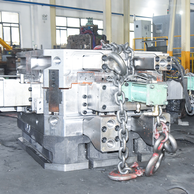 Aluminum Alloy High Pressure Die Casting Mold ManufacturingPrecision die design and manufacturing service for complex, high-precision aluminum parts, using CNC machining and strict dimensional control for mass production.View Product →
Design Details That Decide Whether a Die Works
The same handful of geometry rules come up in almost every die review. They are simple, and they are also the ones most often skipped when a project is under schedule pressure.
Die Materials, Coatings and Service Life
Nearly all aluminium die casting dies are made from hot work tool steel. The grade selected sets a ceiling on how the die behaves at running temperature, and heat treatment decides whether that ceiling is actually reached.
| Steel grade | Typical hardness (HRC) | Heat resistance | Where it fits |
|---|---|---|---|
| 1.2343 (H11) | 43 to 47 | Medium | Complex dies with many slides and deep cavities |
| 1.2344 (H13) | 44 to 48 | Medium to high | General purpose production dies |
| 1.2367 | 46 to 50 | High | Thick walled parts, hot running and long life tools |
Relative heat resistance at a glance
The bars above are a simplified illustration of how the three grades rank against each other in hot strength. They are not measured test data, and the real differences show up mainly under sustained high die temperature.
Hardness is not the only variable. Gas nitriding or plasma nitriding builds a thin hard layer on the cavity surface and often noticeably extends the life of the gate area. Coatings developed for aluminium die casting reduce the tendency of molten metal to stick to the steel. Both treatments depend on clean steel and a properly prepared surface; a nitride layer that is too thick will spall, and the damage will be worse than doing nothing.
For aluminium die casting, die life is normally counted in shots. A well maintained H13 tool running at a controlled alloy temperature can reach six figures of shots; a tool with heat checking, a distorted parting line or blocked cooling channels loses life quickly rather than gradually. Heat treatment practice and steel cleanliness keep improving, and recent progress in high pressure die casting mould design and manufacturing technology is very much about closing that gap between a theoretical life figure and what the tool actually delivers.
One Process, Many Products: How the Die Follows the Application
A die is always built around a specific part, but the logic behind the design shifts with the application. The physics stays the same; the priorities change.
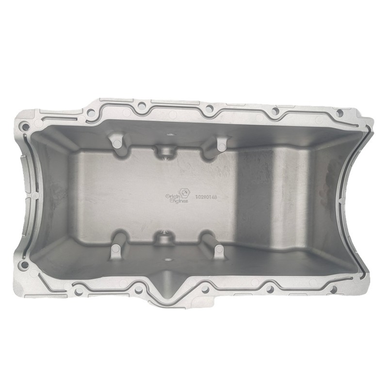
Automotive powertrain parts tend to be thick walled and load bearing. Oil pans, engine mounting brackets, transmission housings and steering components all need generous feeding and careful cooling in heavy sections. The gate has to be positioned so that solidification moves in the right direction and the last metal to freeze is not somewhere that needs to be dense and pressure tight.
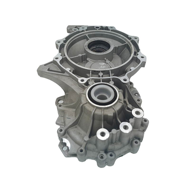
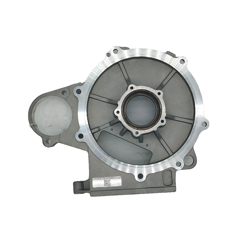 Aluminum Alloy Electric Drive System Die CastingsFor new energy vehicle electric drive systems, these die-cast aluminum housings and casings offer lightweight construction, heat dissipation, and corrosion resistance.View Product →
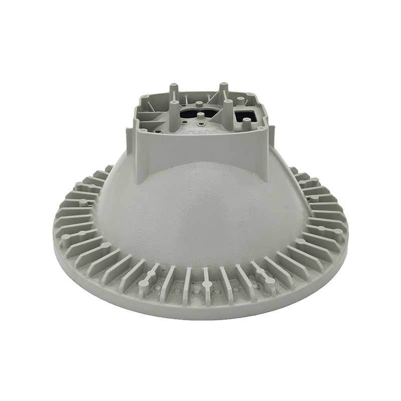
Communication and infrastructure housings sit at the other end of the scale. Base station housings, radar housings and signal transmitter enclosures are usually thin walled, dimensionally demanding, and often need sealing surfaces and a clean appearance. These dies are frequently smaller, but the venting demand is higher, because thin wall filling needs speed and higher speed traps more air.
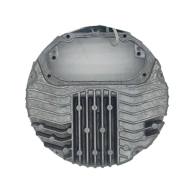
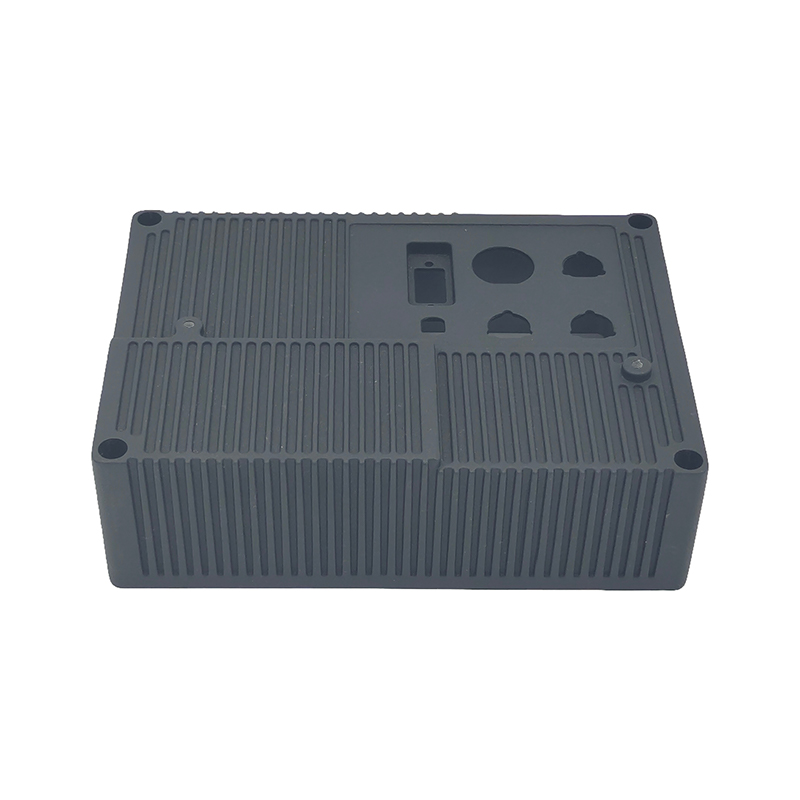 High Pressure Die Cast Aluminum Radar Housing ComponentsRadar housing die-cast components for communication systems, offering high strength, heat dissipation, and corrosion resistance with precision manufacturing and customizable surface treatments.View Product →
In between sit lighting housings, engineering machinery reducer housings, electric scooter structures, photovoltaic inverter parts and furniture hardware. Each asks something slightly different of the tool, but all of them are solved with the same three questions: get the metal in from the right direction at the right speed, give the air a way out, and pull the heat away from where it is doing harm.
Common Casting Defects and What the Die Has to Do With Them
When a casting fails inspection, the conversation often turns to machine settings first. In many cases the root cause is in the tool. These are the defects that most often trace back to a die decision.
Gas porosity
Appears when vents are in the wrong place or the gate shoots metal straight at a cavity wall, so air is carried into the part instead of escaping. The fix usually starts with gate direction and overflow position, not with slowing the machine down.
Shrinkage porosity
Comes from thick sections that do not receive enough feed metal, or from local overheating during solidification. A gate that freezes too early, combined with missing cooling in a heavy wall, is the classic combination.
Cold shuts
Two metal fronts meet after they have already chilled and fail to fuse. Causes include low die temperature, insufficient fill speed, or a gate section that is simply too thin for the wall it has to fill.
Soldering and drag marks
Local overheating, insufficient draft, or a surface treatment that has worn through will let aluminium weld itself to the steel. Once dragging starts it accelerates, because the damaged surface pulls more metal.
Hot cracking
Small radii or unbalanced ejection can tear a casting while it is still hot and weak. This type of failure is nearly always a design issue rather than an operator issue.
Flash
Metal escaping at the parting line points to a worn parting surface, insufficient clamping force, or a die base that deflects under load. A rigid base and a well maintained parting line prevent most of it.
Ejection distortion
Too few ejector pins, or pins concentrated in one area, will bend the casting on the way out. The correction is either more pins or a later ejection point in the cycle.
Keeping a Die Alive
A die rarely fails suddenly. It deteriorates in small, measurable steps, and the maintenance routine is what decides whether those steps are noticed early or discovered during a production stop.
- Inspect the parting surface every shift and clear flash and aluminium debris. A single chip trapped on the parting line can bruise the surface it sits on.
- Confirm cooling flow and temperature at the start of every shift. A blocked line quietly does more damage over a month than a single crash event.
- Lubricate slides and ejector plates on a fixed shot count, not when someone remembers. A seized slide is expensive to recover.
- Record dimensions at defined checkpoints and watch the wear trend. Trends tell you when to pull a die for inspection; a single measurement rarely does.
- Plan strip downs: replace worn ejector pins, dress the parting line, re-nitride where the surface layer has gone. Every strip down is a chance to correct something small.
- Log every change and the shot count it was made at. After a few years, that record is the most reliable design reference you own.
Choosing a Die Casting Die Maker
Die prices are easy to compare and much less easy to interpret, because two quotes for the same part can differ by a lot and both can be honest. What separates them is usually how much engineering sits behind the number.
- Does the supplier run its own die shop? If design and machining stay in house, changing a gate or a slide does not wait for an outside schedule.
- Will you get a filling simulation report, not just a screenshot? A useful report shows fill time, temperature distribution and air entrapment, along with the design changes those results produced.
- Is steel origin and heat treatment traceable? Grade and heat treatment curve have a larger effect on die life than most buyers expect.
- How is trialling handled and what correction scope is included? A die leaving the shop is only the beginning; the first trial is where good parts are really made.
- Does the maker also cast? A supplier that runs both a die shop and die casting machines can validate the tool under real production conditions instead of a one off test.
- What happens to wear parts later? Availability of ejector pins, slide inserts and gate inserts decides how long a production stop lasts.
Running your own die casting mould manufacturing means design, machining and trialling happen under one roof, which shortens the loop between spotting a problem and fixing it. That is the practical difference a vertically integrated supplier brings, and it shows up in the years after delivery rather than on the quotation itself.
Frequently Asked Questions
How long does an aluminium die casting die last?
A well maintained H13 die running at a controlled alloy temperature can reach 100,000 to 200,000 shots or more. Poor cooling, frequent overheating or a neglected parting line can cut that figure dramatically. Life depends more on maintenance and process control than on the steel grade alone.
How long does it take to build a new die?
A typical production die takes a number of weeks from released drawing to first trial, covering design, steel preparation, rough machining, heat treatment, finishing and assembly. Simple single cavity tools move faster; large tools with several slides and complex cooling take longer. Locking the gate strategy early is the single best way to avoid delay.
Is H13 better than 1.2343?
They are close relatives. The 1.2343 grade is slightly tougher, which makes it a common choice for complicated dies with many slides and thin sections. The 1.2344 grade balances toughness and hot strength, which is why it is used as a general purpose standard. Neither is simply better; the match to the part is what counts.
Can a damaged die be welded and reused?
Yes, but with care. A repair weld introduces a heat affected zone, and that zone often becomes the starting point for the next heat check crack. Local repair welding followed by re-nitriding works for small damage. A cavity insert with widespread cracking is usually replaced rather than repaired.
What is the difference between a prototype die and a production die?
A prototype die validates shape and fit early, often with a simplified structure, one cavity and limited life. A production die carries full cooling, balanced ejection and replaceable inserts, and is designed to run reliably for tens of thousands of shots or more.
Why are die casting dies so expensive?
Because they are tools that work hot, under repeated impact loads and high pressure. The steel has to be heat treated to a narrow specification, cooling channels have to be drilled deep into hard blocks, and moving components have to be ground to fine tolerances. A large share of the cost sits in design work and machining that is never visible in the finished tool.


 1 Building No.1 No.226. Tiantaishan Road, Daqi street. Beilun District, Ningbo City, Zhejiang Province, China
 +86-15967858563

