
 English
 Español
 Deutsch
 русский
Every aluminium die casting begins as a drawing, but the quality of the finished part is decided much earlier, in the design of the tool that will produce it. Die cast tool design is the work that sits between a part print and a production-ready mould: choosing the parting line, laying out runners and gates, balancing cooling, deciding where the tool must slide, lift or eject, and confirming that the whole assembly fits the machine it will run on.
It is also where cost is decided. A tool that fills cleanly and cools evenly runs fast and produces few rejects. A tool that fights the metal on the first shot usually keeps fighting for its whole life. Below we share how we approach die cast tool design in our own mould shop, what we check before any steel is cut, and the details that separate a tool that lasts from one that struggles.
What Die Cast Tool Design Actually Covers
People sometimes picture a die casting tool as two blocks of steel with a shape carved into them. In practice a production tool is a system. It has to deliver molten aluminium to the cavity at the right speed and temperature, let air escape ahead of the metal, remove heat at a controlled rate, and push the solidified part out without distortion. Each of those jobs belongs to a different part of the tool, and all of them are settled during design rather than during trial runs.
Good die cast tool design therefore answers four questions at the same time:
- Will the cavity fill completely before the metal freezes?
- Will the part cool evenly enough to hold its shape and dimensions?
- Can the casting be ejected, trimmed and machined without extra handling?
- Will the tool survive the number of shots the program actually needs?
When those four answers line up, the rest of the project usually goes smoothly.
Decisions That Happen Before Steel Is Cut
Most of the value in die cast tool design is created in the review stage. Long before we model inserts and die blocks, we work through the part with the customer's engineers.
Parting line and draft
The parting line determines how the part sits in the tool, where flash will appear, and how simple or complex the tool becomes. It also fixes draft, and draft is not negotiable in die casting. Surfaces that must draw cleanly need enough taper, and the direction of that taper has to respect both the cosmetic and the functional faces of the part.
Wall thickness, ribs and bosses
Thick sections cool slowly and pull metal from thinner neighbours, so we look for heavy walls that can be cored out, ribs that can replace solid mass, and bosses that can be supported with fillets instead of sharp corners. A small change here often removes a large problem later.
Machine fit and shot planning
We also check projected area, locking force, shot weight and die height against the presses we will run. A design that is ideal on paper but does not fit the machine is not a design, it is a delay.
The Anatomy of a Die Casting Tool
It helps to look at a tool element by element. The table below is the checklist we use when reviewing a layout with a customer.
| Tool element | What it does | Design question |
|---|---|---|
| Cavity and core inserts | Form the part geometry | Can the shape be machined, polished and replaced? |
| Shot sleeve, runner and gate | Carry metal into the cavity | Will the cavity fill before the metal freezes? |
| Overflow wells and vents | Release trapped air and cold metal | Is there a path out for gas at every last-fill point? |
| Cooling channels | Remove heat at a controlled rate | Can every thick section be reached? |
| Ejection system | Push the part out without marking or bending it | Are pins placed on strong, non-cosmetic surfaces? |
| Slides, lifters and cores | Form undercuts and side features | Will they move freely after thousands of shots? |
| Die base and guide system | Keep the halves aligned and stable | Is the structure stiff enough for the tonnage? |
From Part Print to Proven Tool: Our Design Workflow
A repeatable sequence keeps tool projects predictable. Ours looks like this:
- Review the part print, the alloy and the expected annual volume.
- Agree the parting line, draft and any geometry changes needed for casting.
- Lay out the cavity, runner, gates, overflows and venting.
- Design the thermal circuit and check it with filling and solidification simulation.
- Complete the 3D tool design, including slides, ejection and the die base.
- Manufacture, assemble and run the first trial, then measure the samples.
- Adjust, re-trial and document the tool before handover to production.
Steps two and three are where most of the money is saved. A gate that is slightly too small is easy to open later; a parting line in the wrong place is not.
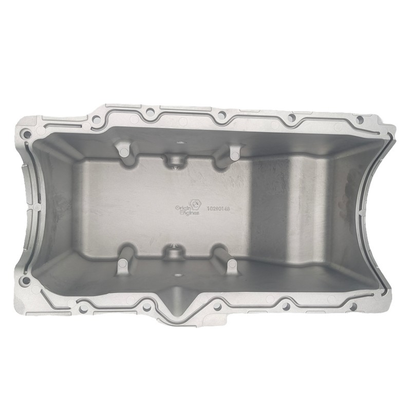
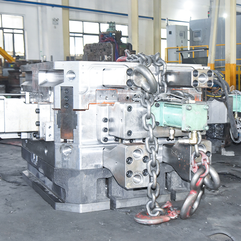 Aluminum Alloy High Pressure Die Casting Mold ManufacturingFor projects where gate and parting-line decisions affect cost, this mold manufacturing service supports complex die-casting structures with CNC machining and precision tolerances.View Product →
Cooling and Thermal Balance: Where Cycle Time Is Won
Cycle time is mostly a thermal question. If one area of the tool stays hot while the rest cools, the part will be ejected too early in one place and too late in another, which shows up as warping, porosity or surface defects.
We design cooling around the part, not around the die base: channels close to heavy sections, baffles or bubblers where the geometry is deep, and separate circuits where a slide or core needs a different temperature. On tight-tolerance housings such as a radar or base station enclosure, the thermal layout also decides whether sealing faces stay flat after machining.
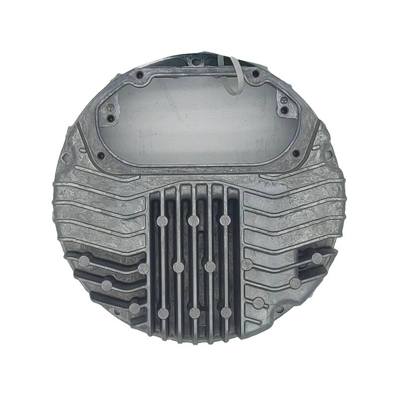
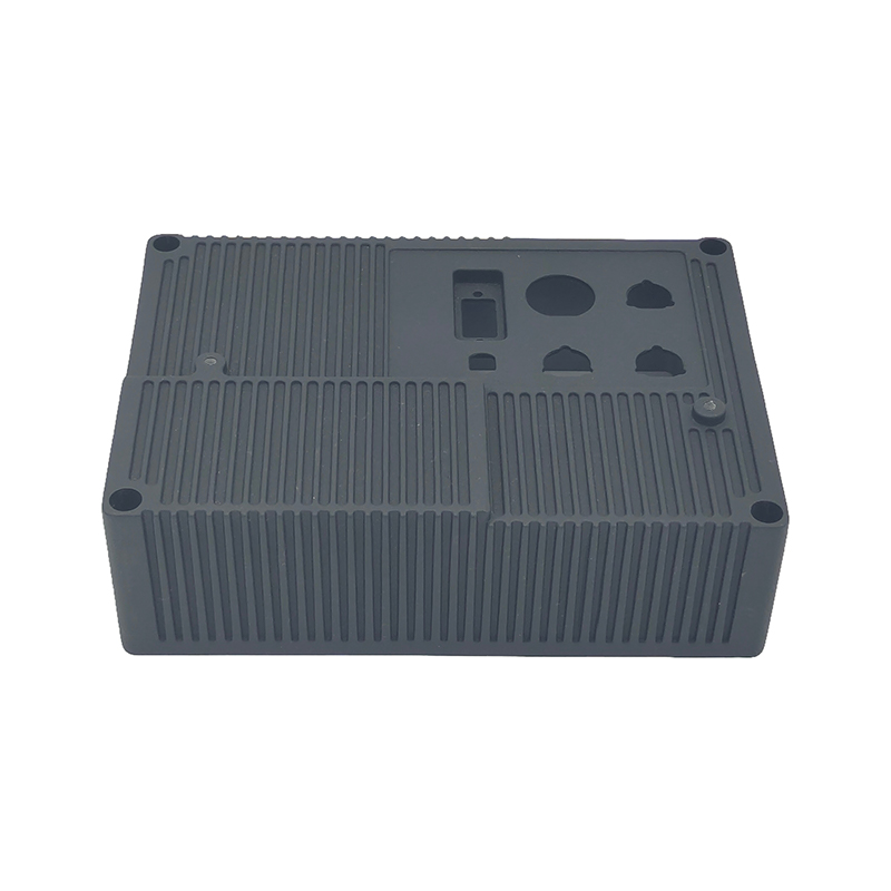 OEM/ODM Aluminum Radar Housing Die CastingsThese aluminum high-pressure die castings provide radar equipment housings with structural protection, heat dissipation, electromagnetic shielding, and options for custom mold design and surface treatment.View Product →
Tool Steel, Wear and Maintenance
Material selection follows the job. Cavity and core inserts are usually cut from hot work die steel, hardened and tempered for a balance of toughness and heat resistance, because a die casting tool sees thermal cycling rather than steady load. Slides, cores and gate inserts may use different grades, and soldering-prone areas sometimes benefit from a surface treatment.
Design also has to think about the day the tool leaves the press. Inserts should be removable, water lines accessible, and wear items replaceable without remachining the die base. Planning spare cavities, gate inserts and ejector pins at design stage turns a two-week stoppage into an afternoon job. The same forward thinking applies downstream, where post-processing choices for deburring, machining and surface finish are easier when the tool already supports them.
Design Mistakes That Show Up on the Production Floor
Some problems are so common that we look for them deliberately:
- Wall thickness assumed to be uniform, instead of checked section by section.
- Gates placed for convenience rather than for the fill pattern.
- Vents too few, too small, or blocked by the ejector layout.
- Cooling lines that miss the thickest sections of the part.
- Ejector pins landing on cosmetic or sealing surfaces.
- Slides that work in CAD but leave no room for wear plates or lubrication.
None of these are exotic. They simply get missed when a tool is designed in a hurry.
How Tool Design Shifts by Application
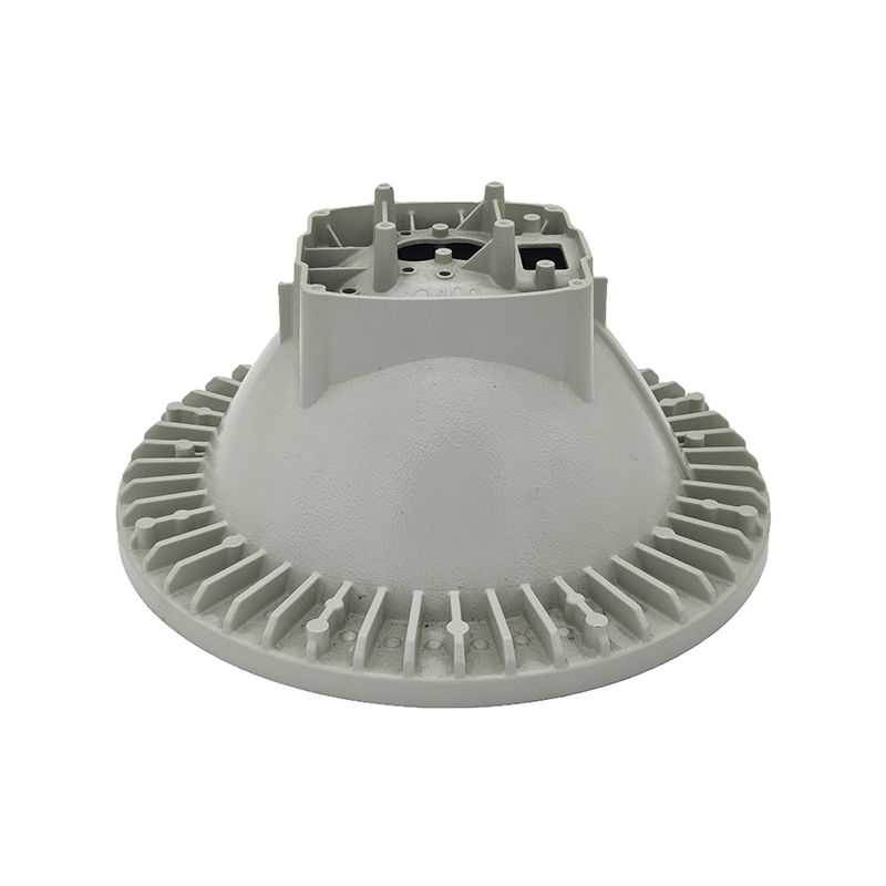
The same method produces very different tools depending on where the casting ends up. A structural automotive part may be judged on strength and internal soundness, while a lighting housing is judged on heat dissipation and appearance. Electric drive and control housings often combine thin walls with machined sealing surfaces, which pushes the thermal design and the ejection plan in opposite directions.
That is why we keep the design conversation tied to the application rather than to a generic template.
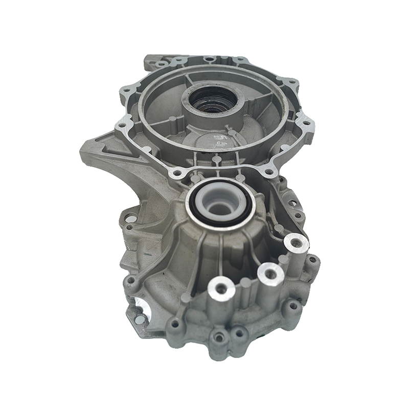
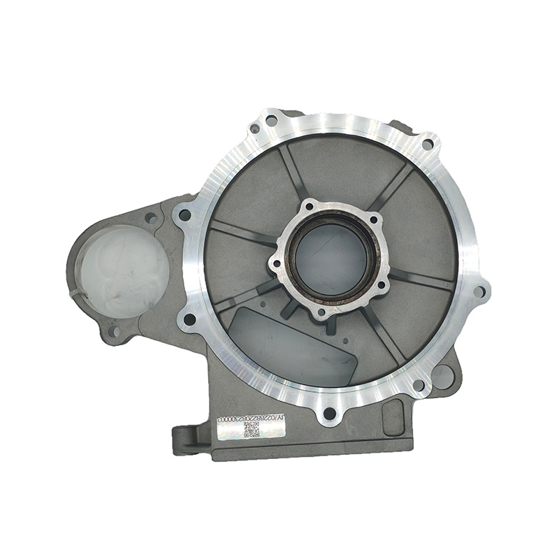 NEV Electric Drive System Aluminum Alloy Die CastingsFor new energy vehicle motors and control modules, these lightweight aluminum die castings offer structural strength, thermal conductivity, corrosion resistance, and precision high-pressure casting.View Product →
Why In-House Tool Building Changes the Conversation
When the people who design the tool also cut it, try it and run it, feedback loops get short. A change suggested in simulation can be tested in the same building, and the engineers who designed the cooling circuit are the ones standing at the press when the first samples come out.
Our mould manufacturing team works alongside the casting and CNC departments, so a design decision is never made in isolation from the machine that will run it or the machining that follows it.
Questions We Hear About Die Cast Tool Design
How long does tool design take?
For a typical aluminium part it is a matter of weeks rather than months, though the review stage depends on how quickly the drawing and the volume forecast are agreed. Rushing that stage almost always costs more time later.
Can one tool be designed for more than one part?
Sometimes. Family tools and interchangeable inserts make sense when the parts share an alloy, a size range and a demand pattern. They make less sense when a change to one part would disturb the thermal balance of the others.
What information do you need to start?
A 3D part model or a clear 2D drawing, the alloy, the expected annual volume, the post-processing steps, and any quality requirements such as pressure tightness or dimensional tolerances.
Die cast tool design is not the most visible part of a casting project, but it is the part that decides how the rest of the project feels. Get the fill, the cooling and the ejection right on paper, and production becomes a matter of discipline rather than firefighting. If you are at the early stage of a part and would like a second opinion on the tool concept, we are always happy to look at the drawing and talk it through.




 1 Building No.1 No.226. Tiantaishan Road, Daqi street. Beilun District, Ningbo City, Zhejiang Province, China
 +86-15967858563

